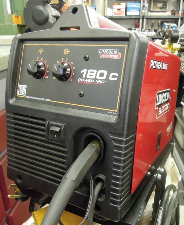
I’m a novice MIG welder. I learned the basics of stick or traditional arc welding many years ago, but have had an interest in learning MIG for some time. So last summer (2012) I bought a new Lincoln 180C from a local welding supply. It’s a great little 230V welder and is about perfect for my small shop.
As I’m learning to weld by my boot-straps, that is, teaching myself, I’ve done (and continue to do) a lot of reading about welding in general and MIG in particular, both on the ‘net and from several well-regarded books. Most reference books refer to machine settings as wire feed speed, typically expressed as Feet Per Minute (FPM) and voltage. However, my Lincoln welder’s dial settings are not calibrated in these terms, but rather voltage is indicated by the letters “A” through “J” and feed speed by the numbers “1” through “10”. These settings don’t cross-reference to printed technical references and Lincoln doesn’t supply any type of cross reference either. However, Lincoln does provide handy reference documentation regarding common metal thickness and wire sizes and what that means for their dial settings.
I’m also the curious sort. I’ve been wondering what is the conversion of the Lincoln alpha/numeric dial settings to the common settings used by reference material, i.e., FPM and volts. So I decided to do something about this and run a series of simple tests to determine feed speed and voltage at each given dial setting. I thought I’d provide my data here in case anyone else had a similar curiosity.
A disclaimer: I don’t contend that my results will match any other, even on identical equipment using the same procedure. There are simply too many variables involved, not the least of which is the variation from machine to machine. My welder is quite new and probably has no more than a couple of hours of actual weld time. Your results may vary but my results are probably in the ball park for the majority of folks.
Test procedure: I used .035 wire for all tests. I started at the bottom of each respective dial and worked my way up to the top of the scale. I then turned the dial back and forth from minimum and maximum slowly twice, then started over at the top of the scale and worked my way back down to the lowest setting. I recorded the measurement at each single setting as I progressed up and down the scale. Therefore, two tests were done on each setting of each dial and I averaged the results. If the results varied more than one measurement in each respective case, I ran two more tests at that setting and average the two closest results. This only happened a couple of times.
For the feed speed, the voltage dial was set to “D” and I triggered and counted to six and multiplied by ten to convert the results to Feet Per Minute. Frankly I was a bit surprised how non-lineal the FPM figures turned out to be.
For voltage I used a good quality digital multimeter across the power terminals, triggering the gun with no wire loaded. I held the trigger until the voltage results stabilized on the meter dial. This represented the open voltage no load condition.
Though probably not the epitome of accuracy, these tests are close enough for my purposes and I’m confident in the results of the test.
In any event, here are my results.
| Voltage | Feed Speed | ||
| Feet Per Minute | |||
| Dial Setting | Voltage | Dial Setting | FPM |
| A | 10.00 | 1 | 50 |
| B | 12.50 | 2 | 80 |
| C | 15.20 | 3 | 125 |
| D | 17.32 | 4 | 170 |
| E | 19.70 | 5 | 195 |
| F | 21.73 | 6 | 210 |
| G | 24.10 | 7 | 250 |
| H | 25.80 | 8 | 295 |
| I | 32.00 | 9 | 320 |
| J | 34.50 | 10 | 495 |
I appreciate the conversion chart–very handy. Lincoln appears to be less than generous with their operating parameters.
just about an hour ago I sent a query to Lincoln regarding the converstion of the letters and numbers on the dials. I then tried a google search about converting letters and numbers and found your video. Thank you!
I have a question: I just received my Lincoln power mig 180C (12/17) and had a bit of a time trying to get the 75/25 gas out of the nozzle – I called Lincoln and Jim, the tech, had me pull the gun cord from the maching and had me when inserting it into the machine to turn it left and right as I inserted it. Finally I had gas flowing. Did you have a problem with this issue?
No, I haven’t had this issue with the gas line. I’d guess it’s a slight tolerance issue, that is, the parts are just slightly at one end or the other of their manufacturing tolerances.
Great info mate, thanks very much! ….I just want to confirm that the wire feed is definitely ‘Feet per minute’ and not ‘Inches per minute’ ? In Australia we use the metric system (decimal)…. and I recently did a basic experiment to check the wire speed and it seems to convert to inches not feeet? (eg. on setting #1, i fed out 1290mm in 1 minute which when divided by 25.41 mm/inch = 50.767 inches) ..am I oing something wrong? Cheers from Australia, Grant
I believe you are correct, it’s INCHES per minute, not feet… otherwise, that would be a lot of wire. Not sure how it slipped by me, but thank you for pointing this out! I’ll have to fix this…
Does your convergence chart apply for flux core wire
I don’t know as I’ve never run flux core through my welder. If you have the same welder but using flux core, it may be applicable.