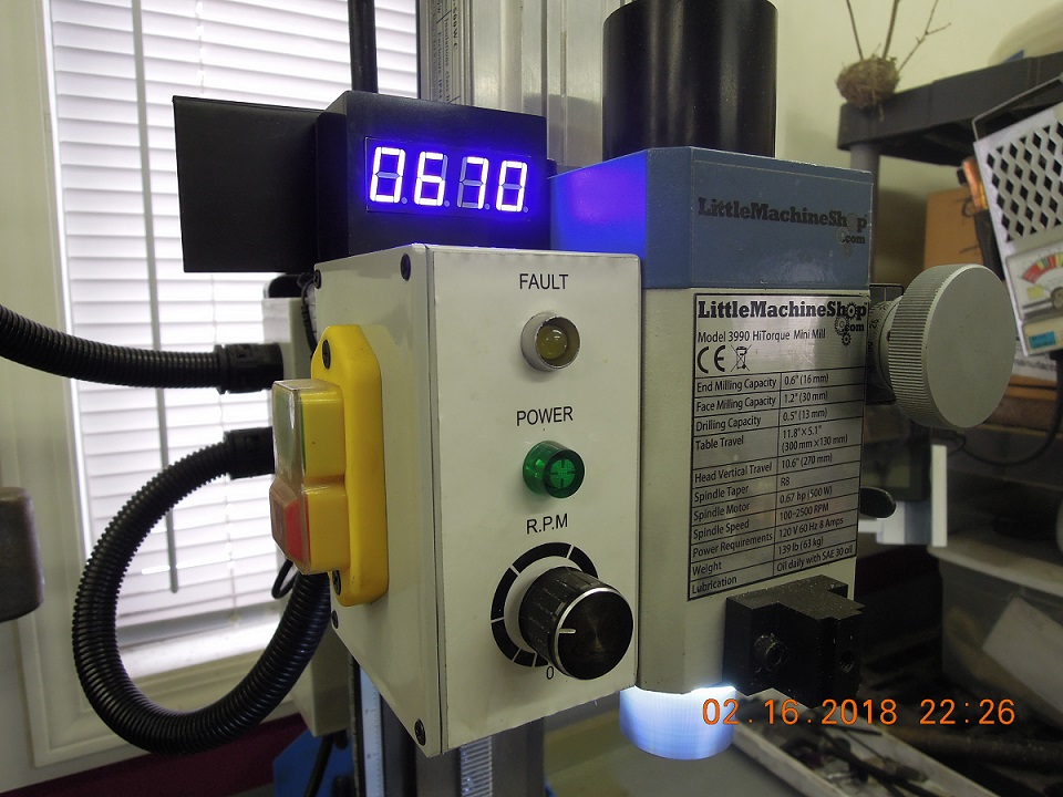
I decided to add a tachometer to my Little Machine Shop 3990 mini mill. After researching the options available, I determined the MacPod tachometer seemed the best solution for my situation. The MacPod unit has a small form factor (size), designed-in integration with the mill, came pre-assembled and was inexpensive.
The next step was to determine how to mount the tachometer. The MacPod circuit board was clearly designed to allow for mounting through the front face plate of the mill control box, which would make for a nice finished install. However, I wanted to minimize modification to the mill and keep it simple. Therefore, I decided to make a simple black plastic box that could be placed externally on top of the mill control panel box. There is a metal plate which comes mounted to the top of the control box that I suspect is provided for the purpose of mounting an aftermarket tachometer. Plus, this allowed for keeping the tachometer up and out of the way and avoid possibly having to make a face plate to protect the unit from exposure to cutting lubricant.
To make the small plastic box, I found inexpensive 1/8 inch thick lack high gloss plastic clip boards in a two-pack at an office supply store. I measured the MacPod circuit board and added just enough to the length and width to allow for comfortable mounting without making the box any larger than necessary. I applied blue painter’s tape to each side of one of the clip boards and and laid out the pieces to be cut for the box. Using a table saw with a fine tooth plywood blade, the material was easy to cut and keep relatively square. Using small machinist squares, the pieces were setup on a surface plate to allow for squaring and alignment during assembly. A general purpose styrene/acrylic thin clear cement was used, applied with a fine artist brush allowing capillary action to draw the cement into the joints. After taping 400 grit sandpaper to the surface plate the joints were cleaned and squared and the original glossy finish was dulled down. I finished with 600 grit paper, which gave a nice flat finish. Note there are many how-to videos on YouTube that detail how to make an acrylic box.
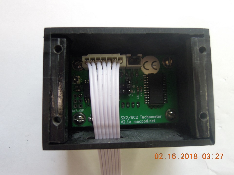
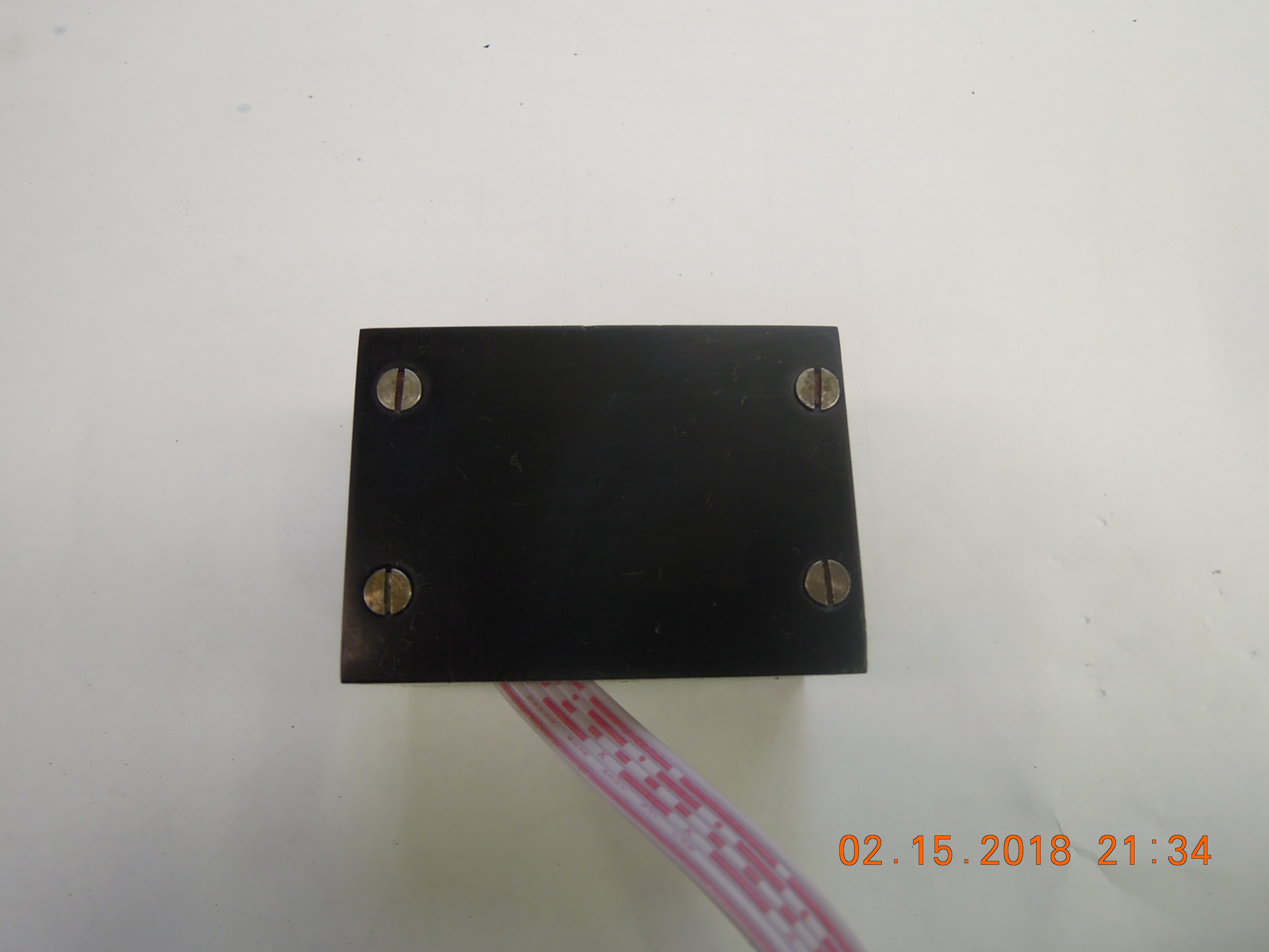
The face plate of the box required a rectangular hole to just allow the circuit board digital readout to show through. I cut the rough opening with a small slitting saw and a Dremel, finishing to size with small files. Before the box assembly was completed, but after the sides and top/bottom were attached to the face plate, I added 4-40 nuts and screws to the circuit board. This was to serve as a template for adding nuts to the inside of the box face plate to have a means of attaching the circuit board. I also cut a 1/8″ slot in the bottom of the box to allow the flat ribbon power/signal cable that connects the tachometer circuit board to the mill mother board to pass through. I roughed up the plastic where the nuts would mount and used two-party epoxy to mount four 4-40 nuts, allowing the epoxy to set overnight. The back plate of the box is mounted with four counter-sunk flat head screws to allow for removal. I added two plastic strips along each side and drilled them to accept the screws for attaching the back plate. A one-inch wide flexible magnetic strip, the kind that comes in a roll with two-sided tape applied and available at any hardware or home improvement store, was attached to the back of the box. This is used to mount the box on the vertical metal plate I mentioned earlier.
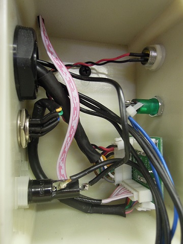
The only modification made to the mill control box was cutting an approximate 1/8″ wide slot long enough to accommodate the ribbon cable, in the top of the box to allow the ribbon cable to pass through into the control box. The only concern here was to align the slot with with the mating slot in the bottom of the plastic box. I did remove the cable from one of the plastic connectors to avoid making the slots any larger than absolutely necessary as the slots would have had to be considerably larger to allow the connector to pass through.
The ribbon cable was feed through both slots, the mounting the box attached to the metal mill plate and the white plastic cable end was reattached to the plastic connector, being careful to ensure proper cable/connector orientation. Then it was simply a matter of unplugging OEM plug that goes to the external tachometer port supplied with the mill from the mill motherboard and plugging the tachometer ribbon cable into the motherboard.
All in all, this was about a half-day project, not including allowing the epoxy to set overnight. Though I haven’t put a lot of time on the MacPod kit yet, I recommend this tachometer, it’s very well designed, inexpensive (about $50.00, w/o shipping) and works exactly as I expected.
There’s also a brief YouTube video that reviews the tachometer kit and the box I fabricated at. https://youtu.be/KH-VtD-0Cak
Looks good Kelly…Hmmm, makes me think about testing Kawasaki triple Oil pump output! Could never figure out a way to maintain the test rpm required by the service manual necessary to measure the pump output volume and compare it to standard. Bet this would work with the mill spinning an oil pump cable at the correct rpm.
Hi Chuck,
Thanks for the comment. Your idea may work, would depend on the RPM required to complete the measurement. The mill tops out at 2500 RPM so as long as the test RPM specification is equal to or less than that, we could give it a try.